flow through the coil, but when the current is turned off, the
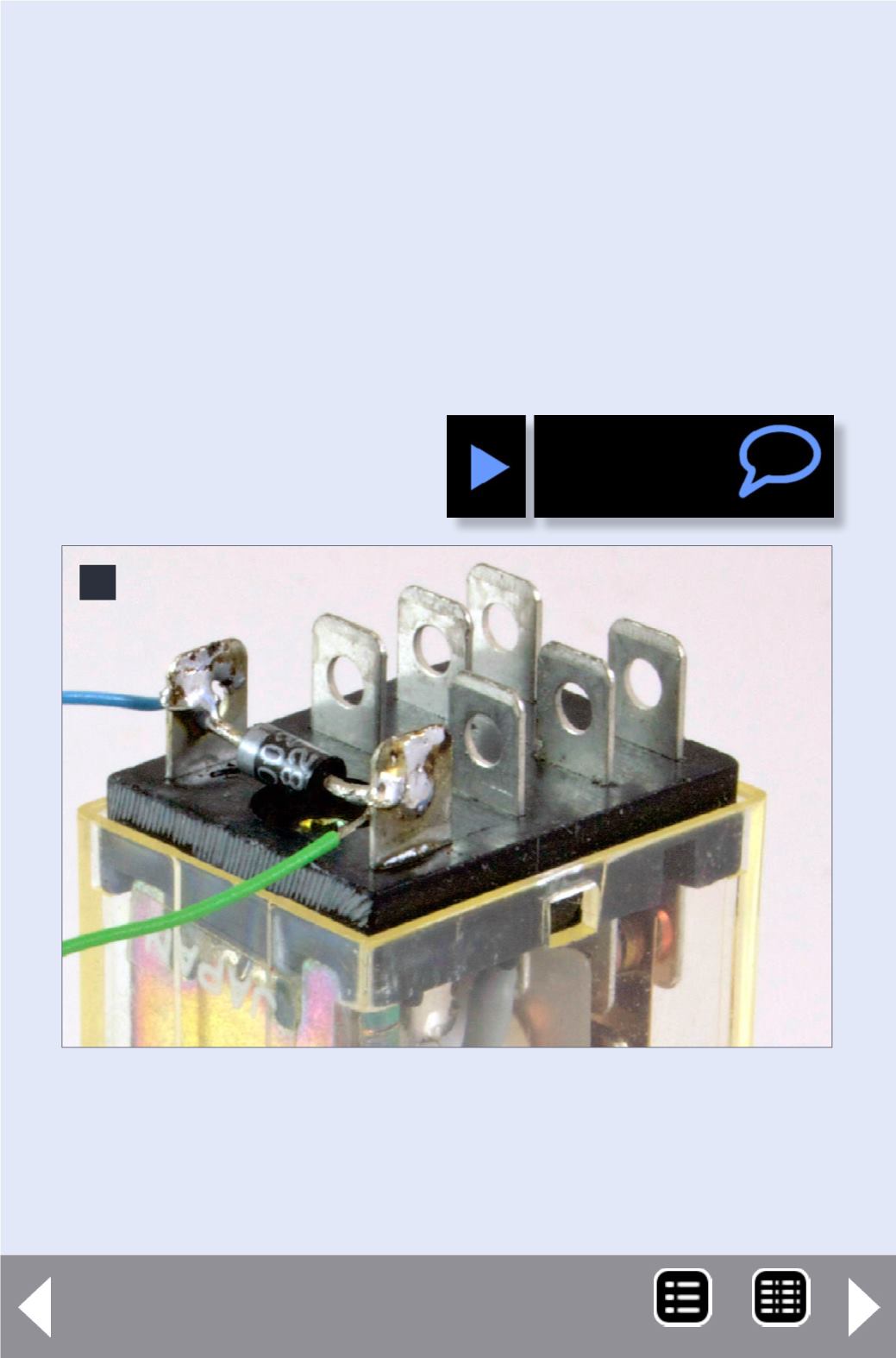
spike of voltage goes through the diode. This means that the
end of the diode with the band connects to the blue (or positive)
wire from the decoder as shown in the detail photo, figure 9.
Select a relay with a coil voltage of 12 volts and an activation
current less than the decoder function output is rated for.
Frequently the functions are rated for 100 mA (0.1 A), so a
coil resistance above 150 ohms is needed. Make sure the
contacts are rated for voltages and currents higher than you
are going to be switching.
9: A diode protects the decoder from being damaged
by the high voltage spike when the decoder drops
the current to the coil. Note: diode band is toward
blue wire. Photo by the author.
9


