Getting Real column - 5
technique described below. Figure 10 shows the completed
cross section of the Celotex roadbed. Diagrams A and B show
how the profile was created.
The basic measurements for HO scale are shown in Diagram
A. The dimensions for other scales are included in the original
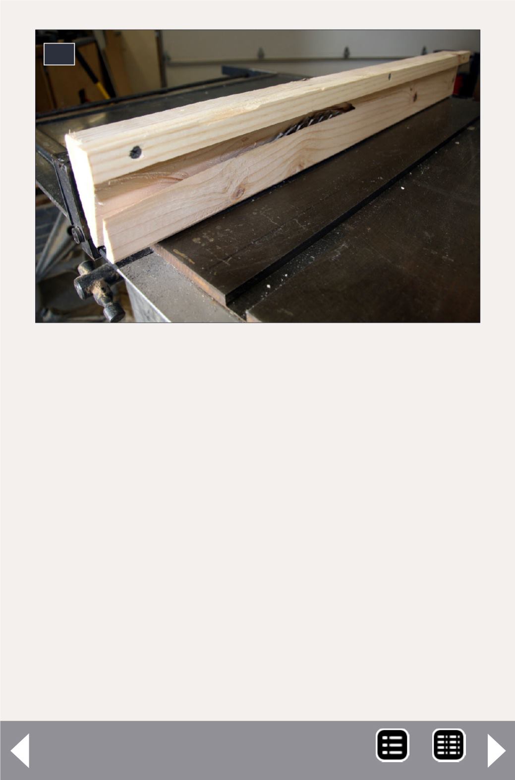
article. Diagram B shows how a length of 2 x 4 was used to
create a jig to cut the ballast slopes. This jig covers the large
portion of blade exposed in making these angle cuts (see dia-
grams A-B).
The 2 x 4 jig is fastened to the saw fence with screws (11). A
second piece of 2 x 4 was clamped to the saw table to hold the
length of Celotex against the jig and blade. Also a strip of wood
was screwed to the top of the jig to hold the piece down on the
11: Jig for cutting roadbed.
11
MRH-Jan 2013


